Boolean Logic
Boolean logic is a type of algebra that deals with binary values or logical values that are either true or false. It is named after the mathematician George Boole. who first introduced the concept in the mid-19th century. Boolean logic is widely used in computer programming, electronics, and digital circuits to control the flow of information and to make decisions.
In Boolean logic, there are three basic operations: AND, OR, and NOT.
The AND operation returns true only if both inputs are true.
The OR operation returns true if at least one input is true.
The NOT operation negates the input means if the input is true then the output is false and vice versa.
Boolean logic can be represented using truth tables. which shows the possible combinations of inputs and their corresponding outputs. Boolean logic is also used to design logic gates.
NOT Gate:-
A NOT gate is also known as an inverter. it is a logic gate that outputs the opposite of its input. It has only one input and one output and the output is the complement of the input.
The truth table for a NOT gate is as follows:
The symbol for a NOT gate is a triangle pointing to the right, with a small circle at its input. The circle represents the negation of the input.
Here is a diagram of a NOT gate:-
In this diagram, the input is on the left side and the output is on the right side. The NOT gate is represented by the triangle pointing to the right, with the circle at its input. When the input is 0, the output is 1, and vice versa.
AND Gate:-
In digital electronics, an AND gate is a logic gate with two or more inputs and one output. The output of an AND gate is "true" (or high, usually represented by the binary value 1) only when all of its inputs are "true". If any input is "false" (or low, usually represented by the binary value 0), then the output of the AND gate is also "false".
The AND gate is one of the basic building blocks of digital circuits and is often used in combination with other gates (such as OR gates, NOT gates, and XOR gates) to create more complex circuits.
It is typically represented in circuit diagrams as the symbol is shown below:

In this diagram, the inputs to the AND gate are represented by the lines coming to the left of the symbol, and the output is represented by the line coming out of the right of the symbol.
The truth table for a 2-input AND gate is as follows:
In this table, "0" represents a false (or low) input, and "1" represents a true (or high) input. The output of the AND gate is "1" (true) only when both of its inputs are "1". In all other cases, the output is "0" (false).
For example, if Input 1 is "0" and Input 2 is "1", the output of the AND gate will be "0", since one of the inputs is false. However, if both Input 1 and Input 2 are "1", then the output of the AND gate will be "1" since both inputs are true.
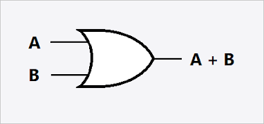
OR Gate:-
An OR gate is a type of logic gate that performs a logical OR operation. It takes two or more input signals and produces a single output signal. The output signal of an OR gate is HIGH (1) if at least one of its input signals is HIGH (1). Otherwise, the output signal is LOW (0).
It is typically represented in circuit diagrams as the symbol is shown below:
The symbol for an OR gate is a plus (+) sign enclosed in a circle. In a two-input OR gate, the inputs are represented by the letters A and B, and the output is represented by the letter Y.
The truth table for a two-input OR gate is as follows:
As you can see from the table. the output of an OR gate is 1 (or high) when either or both of its inputs are 1 (or high). If both inputs are 0 (or low), then the output is 0 (or low).
NAND Gate:-
A NAND gate, short for a "NOT AND" gate, is a type of digital logic gate that performs the opposite function of an AND gate. It has two or more inputs and a single output, and its output is high (1) only when at least one of its inputs is low (0).
The Boolean expression for a two-input NAND gate is:
Z = NOT(A AND B)
- where A and B are the inputs and Z is the output. In other words, the output of a NAND gate is low (0) when both inputs are high (1) and high (1) in all other cases.
- A NAND gate can have more than two inputs, and its output will be high (1) only when all of its inputs are low (0).
- NAND gates are called "universal gates" because any logical function can be constructed using only NAND gates. This means that any digital circuit can be built using just NAND gates, making them a fundamental building block of digital electronics.
It is typically represented in circuit diagrams as the symbol is shown below:
The symbol for a NAND gate is a triangle with a small circle on the output side, and its inputs are represented by lines entering the left side of the triangle.
The truth table for a two-input NAND gate is as follows:
As you can see the output Z of the NAND gate is high (1) in all cases except when both inputs A and B are high (1). In that case, the output is low (0).
The truth table for a NAND gate with more than two inputs will have additional rows for each possible combination of inputs with the output being high (1) only when all of the inputs are low (0).
NOR Gate:-
The NOR gate is a digital logic gate that produces an output of 1 only when both of its inputs are 0. The symbol for a NOR gate is shown below:
It is typically represented in circuit diagrams as the symbol is shown below:
 |
NOR GATE
|
The output of the NOR gate is represented by a line that is connected to the output terminal of the gate. The inputs are represented by lines that are connected to the input terminals of the gate. The circle at the output terminal of the gate represents the inversion of the output which means that the output is low (0) when the input is high (1), and vice versa.
The truth table for a two-input NOR gate is as follows:
As you can see from the table, the output of the NOR gate is 1 (high) only when both inputs are 0 (low). In all other cases, the output is 0 (low).
XOR Gate:-
The XOR (Exclusive OR) gate is a type of logic gate that takes two input signals and produces them.
The symbol for the XOR gate is usually represented by a plus sign inside a circle with one input signal entering at the top and the other entering at the side, and the output signal leaving at the bottom.
The symbol can vary slightly depending on the specific circuit diagram notation being used but here is a common representation:
It is typically represented in circuit diagrams as the symbol is shown below:
In this diagram, A and B are the input signals and the output signal is represented by the arrow pointing downward. The ⊕ symbol in the middle of the gate represents the XOR operation.
The truth table for a two-input XOR gate is as follows:
The XOR (Exclusive OR) gate is a type of logic gate that takes two input signals and produces an output signal based on the following truth table:
As you can see, the output of the XOR gate is 1 (or "true") only when one of the input signals is 1, but not both. If both input signals are either 0 or 1, the output is 0 (or "false").
XOR gates are commonly used in digital circuits and computer systems to perform operations such as addition, subtraction, and data encryption. They can also be combined with other logic gates to create more complex circuits and perform more advanced operations.


Post a Comment